If you remember one number about blast furnace hearth design, make it 1150 °C. That is approximately the temperature at which molten iron begins to solidify, and the position of that isotherm inside the hearth lining determines whether the furnace runs for fifteen years or five. Everything else in hearth refractory engineering — carbon grade selection, ceramic cup design, ramming material, cooling water strategy — ultimately exists to control where that one isotherm sits.
What the Isotherm Actually Does
Molten iron cannot penetrate refractory that is below its solidification temperature — it stops where it freezes. So if the 1150 °C line sits inside the refractory, liquid iron is physically unable to reach the interior of the lining. The region between the hot face and the isotherm is where all the wear happens; everything beyond it is protected. Conversely, if the isotherm migrates outward — toward the shell — the volume of lining exposed to liquid iron grows, and the erosion front advances with it.
This is why hearth condition monitoring tracks thermocouple temperatures so obsessively. The thermocouples are, in effect, sampling the position of the isotherm. A stable temperature profile means the erosion front has stabilised; a steadily climbing temperature in the same location means the isotherm is moving outward and the campaign is being consumed.
How the Isotherm Moves
The isotherm position is set by the balance between heat arriving from the iron and heat leaving through the cooling system. Two things push it outward, and both are common in practice:
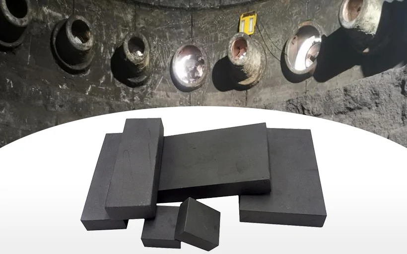
- Insufficient thermal conductivity in the heat path. Heat cannot reach the coolers, so it accumulates and the isotherm moves out. This is the argument for microporous carbon at the hearth sidewall and bottom: its thermal conductivity is several times that of conventional carbon block, which shortens the thermal path resistance and pulls the isotherm inward.
- Voids behind the lining. Gaps between carbon blocks and cooling elements — an unavoidable consequence of tolerances, assembly sequence and shrinkage — act as insulation exactly where conductivity is needed most. A 5 mm air gap conducts almost nothing; it is the weakest link in the entire heat path.
The Counter-Intuitive Fix
When hearth temperatures climb, the instinct is to add refractory thickness. That is often wrong. Adding thickness to a low-conductivity lining moves the hot face further from the cooling system and can push the isotherm outward rather than inward. The correct response is usually higher conductivity in the carbon build-up, a verified cooling circuit, and void filling by water-free injection.
Water-free injection mix deserves emphasis. Injecting a water-bonded material into a hot hearth introduces steam pressure and a localised thermal shock, and the water can carry dissolved species into joints you are trying to seal. A water-free compound restores thermal contact behind the lining without adding water to the system — which is why it has become standard practice for hearth maintenance on medium and large furnaces.
Designing the Heat Path Deliberately
A well-designed hearth treats the heat path as a series circuit, and specifies each element for its role: high-conductivity microporous carbon at the working face, matched ramming mass to eliminate assembly gaps, a ceramic cup where the goal is to protect the carbon from initial erosion during early campaign operation, and cooling water flow rates verified to remove the design heat load. A weakness in any element of the series dominates the whole path — which is why hearth packages should be engineered, not assembled from catalogue items.
Reading the Temperature Trend Like an Engineer
Hearth thermocouple data rewards trend analysis over absolute values. A single high reading on a day of high production rate or high silicon in the hot metal tells you little; the same thermocouple climbing steadily over six weeks tells you the erosion front at that location is advancing. The disciplined approach is to normalise readings against production variables, plot them per location, and look for divergence between neighbouring measurement points. A single point climbing while its neighbours hold steady often indicates a localised issue — a cooling element losing performance, a void developing behind the lining — rather than general erosion.
Two thresholds matter in practice. The first is the alarm level set during design, calculated from the thermal model with the lining at its expected residual thickness. The second, less discussed, is the rate threshold: a modest temperature that is rising quickly is more urgent than a higher temperature that has been stable for a year. Plants that track rate alongside level catch problems while the response is still an injection or an operating adjustment, rather than an unplanned campaign event.
Where Ceramic Cup Fits
The ceramic cup exists to protect the carbon structure during early campaign operation, when the hearth has not yet developed its protective freezing layer. A cup of corundum or chrome-corundum materials takes the first months of erosion so the carbon behind it never sees unshielded iron contact. In well-executed designs the cup then stabilises as a frozen iron/slag layer forms on its face, and the carbon structure — the long-term structural element of the hearth — is effectively never worked. The design detail that matters is the joint between cup and carbon: differential expansion between oxide and carbon materials must be absorbed by the joint design and the ramming mass, or the cup cracks and the protection it provides is compromised at exactly the locations where cracking concentrates.
The Series-Circuit View, Summarised
A well-designed hearth treats the heat path as a series circuit and specifies each element for its role: high-conductivity microporous carbon at the working face, matched ramming mass to eliminate assembly gaps, a ceramic cup to shield the carbon during early operation, and cooling water flow verified to remove the design heat load. A weakness in any element of the series dominates the whole path — which is why hearth packages should be engineered as a system, not assembled from catalogue items selected on individual price.
We have applied this logic on furnace projects from 1,000 m³ to 5,800 m³, including integrated BF and ladle supply at MMK Magnitogorsk. If you are seeing a rising temperature trend in your hearth thermocouples, send us the data and the furnace drawing — we will look at the thermal path with you and identify which element of the series is limiting before you commit to a reline or an injection programme.
For a closer look at the materials in the heat path, see our microporous carbon brick and water-free injection mix pages, or the full blast furnace refractory system overview.